Home
Download PDF
Order CD-ROM
Order in Print
Figure 29. Check Valve Line at Air Control Valve.
Figure 31. Cab Step.
Field Maintenance Manual For Military 621G Scraper -5
Page Navigation
996
997
998
999
1000
1001
1002
1003
1004
1005
1006
TM
5-3805-296-23-5
0359
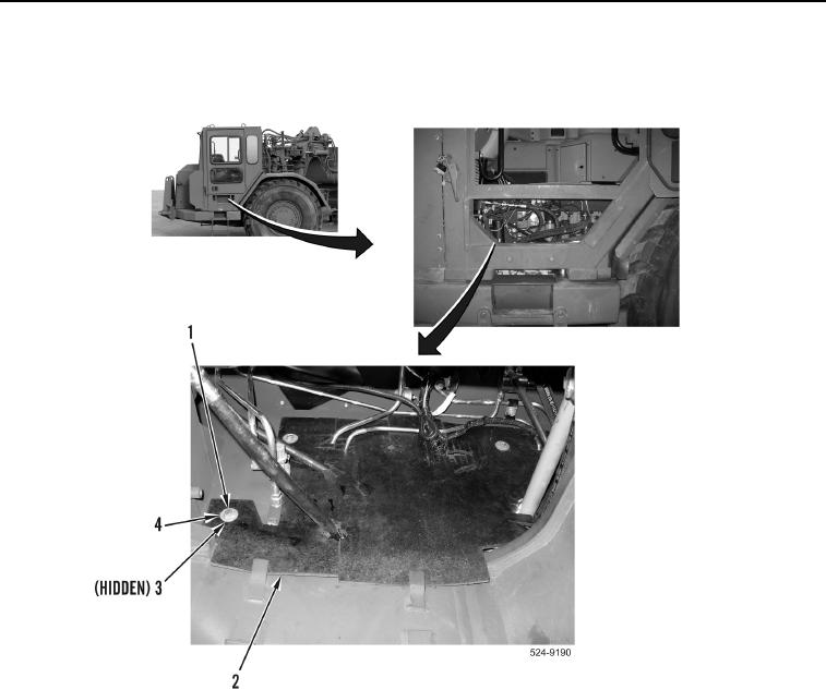
INSTALLATION
CONTINUED
46.
Install
splash
guard
(Figure
30,
Item
2),
four
spacers
(Figure
30,
Item
3),
washers
(Figure
30,
Item
4),
and
bolts
(Figure
30,
Item
1) on
machine.
Figure
30.
Splash
Guard.
0359
0359-31