
TM 5-3805-296-23-5
0359
REMOVAL CONTINUED
CAUTION
Plug and cap all air lines and fittings to prevent contamination. Failure to follow this
caution may result in equipment damage.
NOTE
Tag and mark air lines to aid in installation.
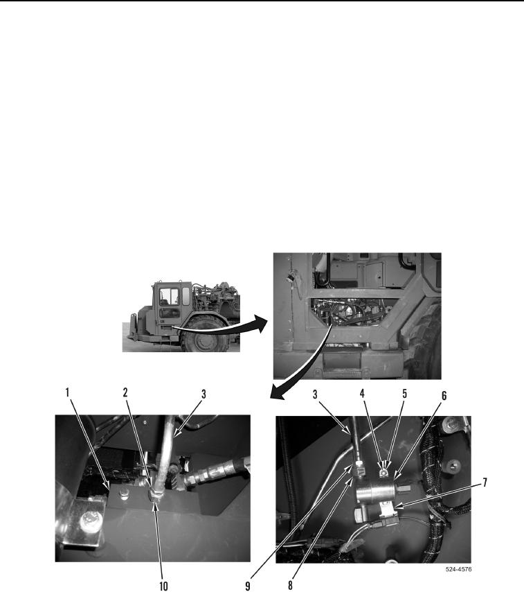
13. Remove tube nut (Figure 5, Item 2) from fitting (Figure 5, Item 10).
14. Remove tube nut (Figure 5, Item 9) from fitting (Figure 5, Item 8).
15. Remove two bolts (Figure 5, Item 4), washers (Figure 5, Item 5), pressure switch (Figure 5, Item 6), and
bracket (Figure 5, Item 7) from machine. Position pressure switch and bracket aside.
16. Remove air line (Figure 5, Item 3) from fittings (Figure 5, Items 8 and 10).
17. Remove fitting (Figure 5, Item 10) from center union block (Figure 5, Item 1).
Figure 5. Pressure Switch to Center Union Block Line.
0359