• Home
  • Download PDF
  • Order CD-ROM
  • Order in Print
Figure 3. Fittings.
Figure 5. Air Line.

Field Maintenance Manual For Military 621G Scraper -5 Page Navigation
  499    500    501    502    503  504  505    506    507    508    509  
img
.
TM 5-3805-296-23-5
0330
INSTALLATION CONTINUED
2. Position front brake actuator (Figure 4, Item 1) on machine.
NOTE
Install air lines location as noted during removal.
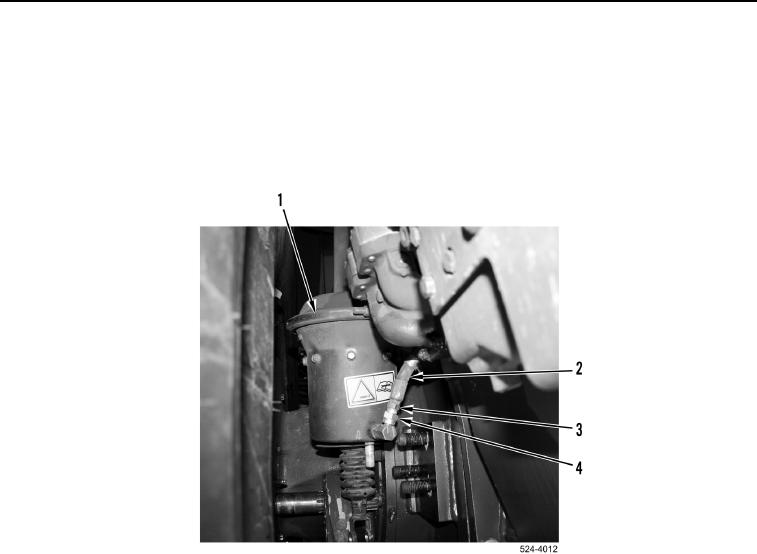
3. Install air line (Figure 4, Item 2) and tighten tube nut (Figure 4, Item 3) on fitting (Figure 4, Item 4).
Figure 4. Air Line.
0330
0330-4


Privacy Statement
Press Release
Contact

© Copyright Integrated Publishing, Inc.. All Rights Reserved.