
TM 5-3805-296-23-5
0324
ASSEMBLY CONTINUED
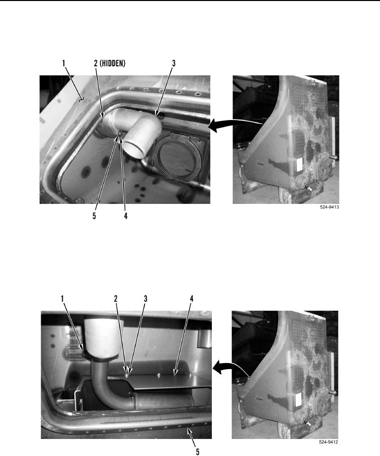
10. Install new O-ring (Figure 37, Item 2), upper elbow (Figure 37, Item 3), two washers (Figure 37, Item 5), and
new lock bolts (Figure 37, Item 4) on hydraulic oil tank (Figure 37, Item 1).
Figure 37. Upper Elbow.
0324
11. Install baffle (Figure 38, Item 4), five washers (Figure 38, Item 3) and new lock bolts (Figure 38, Item 2) on
hydraulic oil tank (Figure 38, Item 5).
12. Install line (Figure 38, Item 1) in hydraulic oil tank (Figure 38, Item 5).
Figure 38. Baffle.
0324