
TM 5-3805-296-23-5
0324
DISASSEMBLY CONTINUED
NOTE
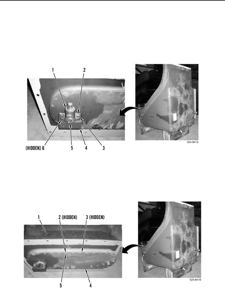
Note position and orientation of drain valve to aid in installation.
26. Remove plug (Figure 30, Item 5) from drain valve (Figure 30, Item 1).
27. Remove two bolts (Figure 30, Item 2), washers (Figure 30, Item 3), drain valve (Figure 30, Item 1) and O-ring
(Figure 30, Item 6) from drain block (Figure 30, Item 4). Discard O-ring.
Figure 30. Drain Valve.
0324
NOTE
Note position and orientation of lower cover to aid installation.
28. Remove 36 locknuts (Figure 31, Item 2), bolts (Figure 31, Item 5), lower cover (Figure 31, Item 4), and gasket
(Figure 31, Item 3) from hydraulic tank (Figure 31, Item 1). Discard locknuts and gasket.
Figure 31. Lower Cover.
0324