
TM 5-3805-296-23-5
0310
JUNCTION BLOCK INSTALLATION
000310
NOTE
Route cables as noted during removal.
Install electrical connections as noted during removal.
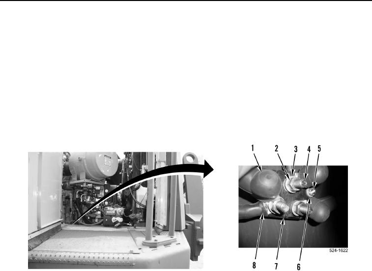
1. Install junction block (Figure 15, Item 7) on machine.
2. Install two washers (Figure 15, Item 6) and bolts (Figure 15, Item 5) on junction block (Figure 15, Item 7).
3. Install five cables (Figure 15, Item 8) on junction block terminals (Figure 15, Item 4).
4. Install three washers (Figure 15, Item 3) and nuts (Figure 15, Item 2) on junction block terminals
(Figure 15, Item 4).
5. Position three covers (Figure 15, Item 1) on junction block terminals (Figure 15, Item 4).
Figure 15. Junction Block.
0310
END OF TASK