
TM 5-3805-296-23-5
0305
INSTALLATION CONTINUED
NOTE
Install wiring harness as noted during removal.
Install P-clamp as noted during removal.
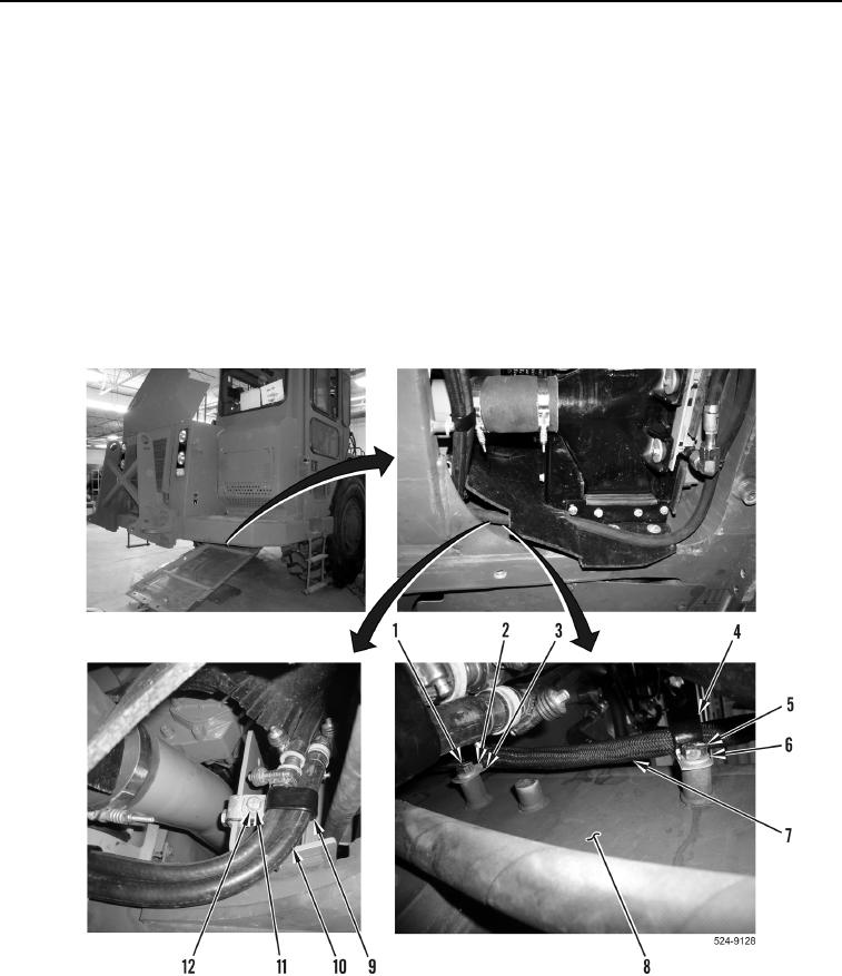
15. Install P-clamp (Figure 14, Item 3) on chassis wiring harness (Figure 14, Item 7).
16. Install P-clamp (Figure 14, Item 3), washer (Figure 14, Item 2), and bolt (Figure 14, Item 1) on frame
(Figure 14, Item 8).
17. Install P-clamp (Figure 14, Item 4) on chassis wiring harness (Figure 14, Item 7).
18. Install P-clamp (Figure 14, Item 4), washer (Figure 14, Item 6), and bolt (Figure 14, Item 5) on frame
(Figure 14, Item 8).
19. Position hoses (Figure 14, Item 10) on machine and install bolt (Figure 14, Item 11) and washer (Figure 14,
Item 12) on P-clamp (Figure 14, Item 9).
I
Figure 14. Chassis Wiring Harness P-clamp Under Baffle.
0305