
TM 5-3805-296-23-4
0280
BOWL CYLINDER PILOT HOSE REMOVAL CONTINUED
CAUTION
Plug and cap all hydraulic hoses lines, and fittings to prevent contamination. Failure to
follow this caution may result in damage to equipment.
NOTE
Tag and mark hydraulic hoses to aid in installation.
Note routing and location of hydraulic hoses to aid in installation.
Note location of clamp to aid in installation.
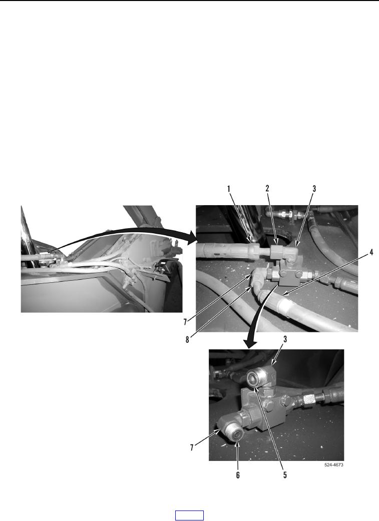
2. Loosen tube nut (Figure 19, Item 2) and remove hose (Figure 19, Item 1) from fitting (Figure 19, Item 3).
3. Remove hose (Figure 19, Item 1) from machine.
4. Remove O-ring (Figure 19, Item 5) from fitting (Figure 19, Item 3). Discard O-ring.
5. Loosen tube nut (Figure 19, Item 8) and remove hose (Figure 19, Item 4) from fitting (Figure 19, Item 7).
6. Remove O-ring (Figure 19, Item 6) from fitting (Figure 19, Item 7). Discard O-ring.
Figure 19. Upper Pilot Control Valve.
0280