
TM 5-3805-296-23-4
0271
REMOVAL CONTINUED
CAUTION
Plug and cap all air hoses and fittings to prevent contamination. Failure to follow this
caution may result in equipment damage.
NOTE
Tag and mark wiring harness connectors to aid in installation.
Tag and mark air lines and hoses to aid in installation.
Note location and quantity of tiedowns to aid in installation.
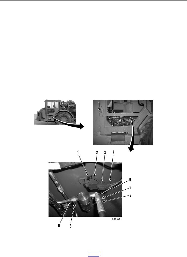
2. Disconnect machine wiring harness connector (Figure 2, Item 4) from differential lock solenoid connector
(Figure 2, Item 3).
3. Remove tiedown strap (Figure 2, Item 1) from differential lock solenoid wiring (Figure 2, Item 2) and machine.
Discard tiedown strap.
4. Loosen tube nut (Figure 2, Item 6) and remove air hose (Figure 2, Item 7) from fitting (Figure 2, Item 5).
5. Remove air line (Figure 2, Item 9) from fitting (Figure 2, Item 8).
Figure 2. Wiring Connector.
0271