
TM 5-3805-296-23-4
0269
REMOVAL CONTINUED
NOTE
Tag and mark fittings, adapter, and plug to aid in installation.
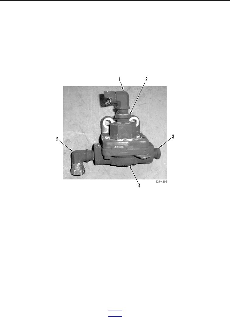
6. Remove fitting (Figure 3, Item 1) from fitting (Figure 3, Item 2).
7. Remove fitting (Figure 3, Item 2) from differential lock quick release valve (Figure 3, Item 4).
8. Remove plug (Figure 3, Item 3) from differential lock quick release valve (Figure 3, Item 4).
9. Remove fitting (Figure 3, Item 5) from differential lock quick release valve (Figure 3, Item 4).
Figure 3. Differential Lock Quick Release Valve.
0269
END OF TASK
CLEANING AND INSPECTION
000269
Clean and inspect all components IAW Mechanical General Maintenance Instructions (WP 0539).
END OF TASK