
TM 5-3805-296-23-4
0266
REMOVAL CONTINUED
NOTE
Note routing of wiring harness to aid in installation.
Tag and mark wiring harness connectors to aid in installation.
Note location and quantity of tiedown straps to aid in installation.
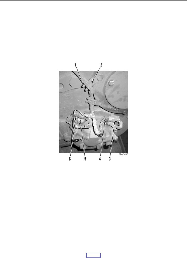
34. Remove two tiedown straps (Figure 13, Item 2) from ladder clips (Figure 13, Item 1). Discard tiedown straps.
35. Disconnect two transmission wiring harness connectors (Figure 13, Items 4 and 6) from connectors
(Figure 13, Items 3 and 5).
Figure 13. Speed Sensor Connectors.
0266