
TM 5-3805-296-23-4
0262
REMOVAL CONTINUED
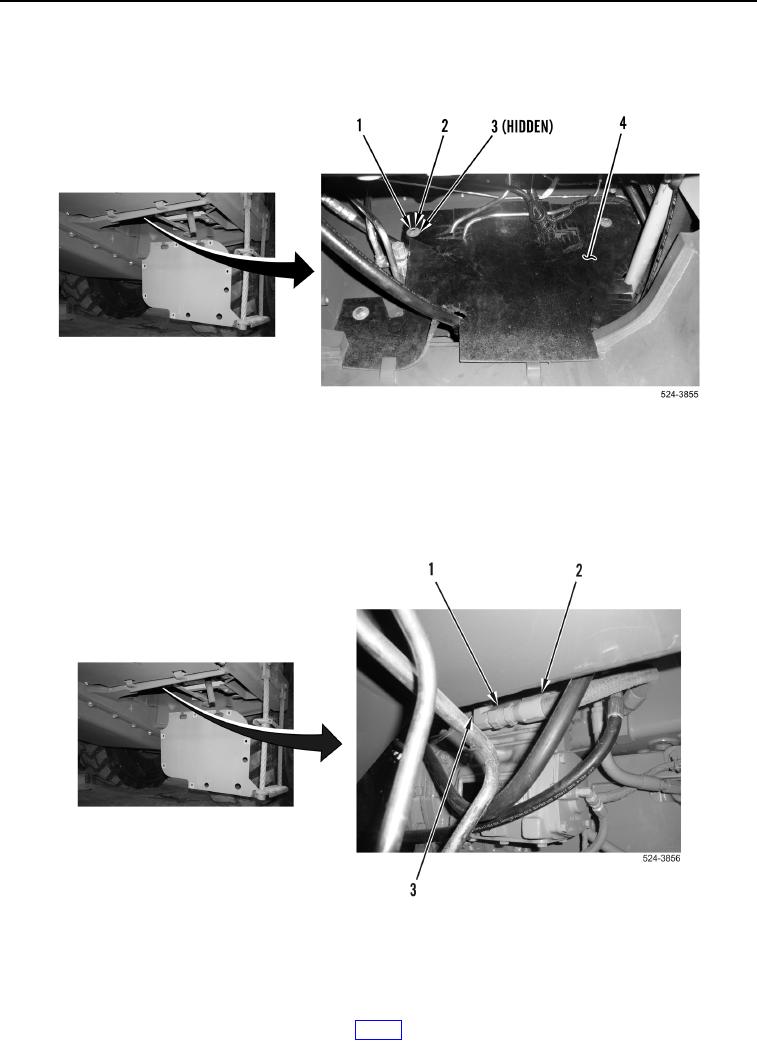
5. Remove four bolts (Figure 3, Item 1), bushings (Figure 3, Item 3), and washers (Figure 3, Item 2) from splash
shield (Figure 3, Item 4). Remove splash shield from machine.
Figure 3. Splash Shield.
0262
NOTE
Note routing and location of air hoses to aid in installation.
6. Loosen tube nut (Figure 4, Item 1), and remove air intake hose (Figure 4, Item 2) from fitting (Figure 4, Item 3).
Figure 4. Air Intake Hose and Air Compressor.
0262