
TM 5-3805-296-23-4
0262
REMOVAL CONTINUED
NOTE
Note routing and location of air hoses to aid in installation.
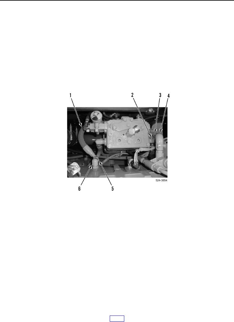
2. Loosen tube nut (Figure 2, Item 5), and remove air intake hose (Figure 2, Item 1) from fitting (Figure 2, Item 6).
3. Slide clamp (Figure 2, Item 3) away from fitting (Figure 2, Item 2).
NOTE
Note routing and location of coolant hose to aid in installation.
4. Remove coolant hose (Figure 2, Item 4) from fitting (Figure 2, Item 2).
Figure 2. Air Intake Hose and Cylinder Head.
0262