
TM 5-3805-296-23-4
0251
INSTALLATION CONTINUED
NOTE
Refer to removal for tiedown strap quantity and location.
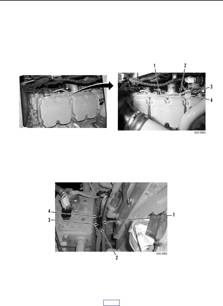
15. Install new tiedown straps (Figure 15 Item 2) on basic engine wiring harness (Figure 15, Item 1).
16. Connect basic engine wiring harness connector (Figure 15, Item 3) to injector wiring harness connector
(Figure 15, Item 4).
Figure 15. Injector Connector.
0251
17. Connect basic engine wiring harness connector (Figure 16, Item 1) until tab (Figure 16, Item 3) engages
camshaft speed timing sensor connector (Figure 16, Item 4).
18. Slide lock tab (Figure 16, Item 2) to lock position on camshaft speed timing sensor connector
(Figure 16, Item 4).
Figure 16. Camshaft Speed Timing Sensor.
0251