
TM 5-3805-296-23-2
0136
Table 1. One or Both Blackout Tail Lights Do Not Operate Continued.
0136
MALFUNCTION
TEST OR INSPECTION
CORRECTIVE ACTION
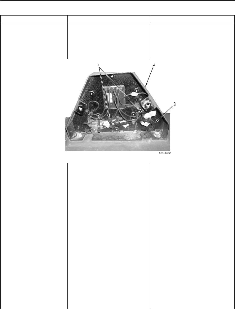
4. Remove two tiedown straps
One or Both Blackout Tail
(Figure 9, Item 1) from wiring
Lights Do Not Operate
harness (Figure 9, Item 3) and rear
Continued
blackout lamp housing
(Figure 9, Item 2). Discard tiedown
straps.
Figure 9. Tiedown Straps.
0136
5. Disconnect connector AH-C9
(WP 0012, Figure 180) from
connector GND
(WP 0012, Figure 175).
6. Disconnect connector AH-C7
(WP 0012, Figure 178) from
connector 24
(WP 0012, Figure 175).
7. Turn battery disconnect switch to
ON position (TM 5-3805-296-10).
8. Turn mode switch on military light
switch to B.O. DRIVE position
(TM 5-3805-296-10).
9. Using digital multimeter
Voltage 18 to 26 V Replace right rear
(WP 0540), test for voltage
blackout lamp (WP 0352).
between connector AH-C7
Proceed to Test Step 20.
(WP 0012, Figure 178) and
Voltage Less Than 18 V Replace tail
connector AH-C9
lights/backup alarm wiring harness
(WP 0012, Figure 180).
(WP 0351).
Proceed to Test Step 20.