
TM 5-3805-296-23-1
0039
Table 1. 1589 Turbo Inlet Pressure Sensor Diagnostic Codes Continued.
039
CID FMI
TEST OR INSPECTION
CORRECTIVE ACTION
Test Step 2. Test for Shorted Engine
1589-04 Turbo Inlet Air
Interface Wiring Harness.
Pressure Sensor Voltage
1. Turn ignition switch and battery
Below Normal Continued
disconnect switch to OFF position
(TM 5-3805-296-10).
2. Lower left frame access plate
(WP 0376).
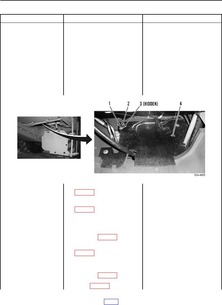
3. Remove four bolts
(Figure 4, Item 1), washers
(Figure 4, Item 2), bushings
(Figure 4, Item 3), and splash
shield (Figure 4, Item 4) from
machine.
Figure 4. Splash Shield and Retaining Hardware.
0039
4. Disconnect connector CM-C1
(WP 0012, Figure 30) from engine
ECM.
5. Disconnect connector CL-C1
(WP 0012, Figure 45) from engine
ECM.
6. Using digital multimeter
Continuity Replace engine interface
(WP 0540), test for continuity
wiring harness (WP 0211).
between connector CL-C1
Proceed to Test Step 3.
terminal 15 (WP 0012, Figure 45)
No Continuity Proceed to step 7.
and all other terminals
in connector CL-C1
(WP 0012, Figure 45).
7. Using digital multimeter
Continuity Replace engine interface
(WP 0540), test for continuity
wiring harness (WP 0211). Replace
between connector CL-C1
basic engine wiring harness (WP 0251).
terminal 15 (WP 0012, Figure 45)
Proceed to Test Step 3.
and all terminals in connector
No Continuity Proceed to step 8.
CM-C1 (WP 0012, Figure 30).