
TM 5-3805-296-10
0004
OPERATOR CONTROLS AND INDICATORS CONTINUED
Switch Panel
0004
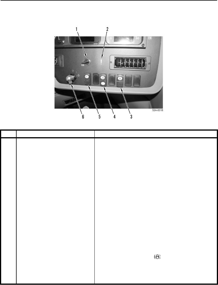
Figure 8. Switch Panel.
0004
KEY
COMPONENT
DESCRIPTION
1
Power Receptacle (12V)
Used to power electrical equipment or accessories.
2
Action Lamp
Illuminates when a problem occurs with machine.
N OT E
3
Mode Select Switch
Functions 1-5 are accessible to the
operator. Functions 6-8 are not.
Press and hold top of switch to scroll through different modes
(functions) on digital display window. Modes include hours,
miles, RPM, service codes, and digital readouts for quad
gauge module.
4
Bowl and Cutting Edge Flood Lamp
Press top of switch to activate bowl and cutting edge flood
Switch
lamps.
Press bottom of switch to deactivate bowl and cutting edge
flood lamps.
5
Brights Switch
Only works with military light switch on SER DRIVE mode.
Press bottom of switch to activate low-beams.
Press middle or top of switch to activate high-beams.
6
Ignition Switch
Turn switch clockwise to on (I) position to activate electrical
circuits in cab.
Turn switch clockwise to start
position to start engine.
Turn switch counterclockwise to off position (O) to shut off
engine and electrical power.
If engine fails to start, switch must be returned to the off
position (O) before attempting to start engine.