
TM 5-3805-296-10
0003
ELECTRICAL SYSTEM
0003
1. The electrical system consists of four 12-volt batteries connected in series, with negative grounding, providing
24 volts to operate the electrical systems and components.
2. The system contains all the necessary switches, circuit breakers, fuses, relays, harnesses, and connectors to
operate the machine, including a NATO slave receptacle.
3. The three major systems comprising the electrical system are:
a. Starting system
b. Charging systems
c.
Service, work, and blackout lights
HYDRAULIC SYSTEM
0003
1. General.
a. The machine hydraulic system supports both the steering and scraper hydraulic systems.
b. The hydraulic system consists of a vane-type pump and a gear-type pump; control, check and spool type
valves; filters; hydraulic motor; lines, hoses and fittings; oil cooler; and hydraulic reservoir. The vane-type
pump mounted on the differential provides hydraulic system pressure for the bowl, ejector, and apron
controls. The gear-type pump (supplemental steering pump), located beneath engine on front of differential
case and frame, adds to the volume of flow in the scraper hydraulics. Since this pump is ground-driven by
forward motion of the machine, the amount of oil it adds is directly proportional to machine speed. If the
vane-type pump loses drive power, the supplemental steering pump supplies hydraulic pressure for
operation of steering only. This allows the machine, in motion, to be steered safely to a stop.
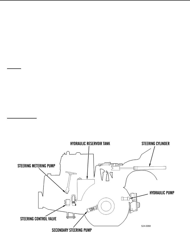
2. Steering System. The steering system is divided into two separate systems: a primary system and a
supplemental system. The primary system shares the main hydraulic circuit with the cylinders for bowl, ejector,
and apron control. A vane-type two-stage pump powers the primary steering system. A separate ground-driven
hydraulic pump powers the supplemental steering system. Both systems operate from a common reservoir.
Figure 4. Steering Operation.
0003