
TM 3-4240-302-30&P-3
Section III MAINTENANCE PROCEDURES
2-7. PROTECTIVE ENTRANCE CONTROL MODULE.
This task covers the removal, 'disassembly, repair, reassembly and installation of the following:
f.
Dome light DS2 (p. 2-38)
a. Housing/panel (p. 2-33)
g.
Switching card A3 (p. 2-39)
b. Toggle switch S3 (p. 2-34)
h.
Power card Al (p. 2-40)
c. LOW PRESSURE switch/indicator light
i.
Pressure transducer MT1 (p. 2-41)
DS4/S5 (p. 2-35)
j.
Female hose adapter (p. 2-42)
d. PURGE indicator light DS3 (p. 2-36)
k.
Male hose adapter (p. 2-43)
e. Interval TIMER switch S4 (p. 2-37)
I.
Wiring (p. 2-44, 2-45)
INITIAL SETUP
Tools
Troubleshooting References
Electronic Equipment Tool Kit
Refer to page 2-2
TK-105/G
Equipment Condition
References
PECM removed from the protective entrance
TB SIG 222
LOCATION
ITEM
ACTION
DISASSEMBLY
Protective Entrance
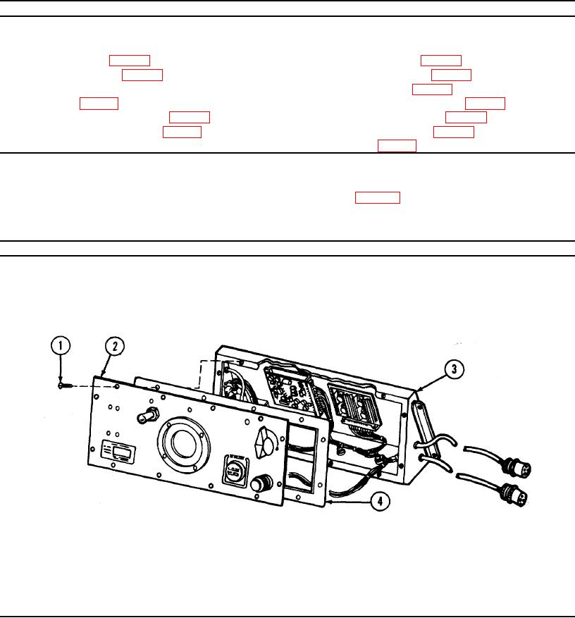
Housing/panel
1. Remove twelve screws (1) from panel (2).
Control Module
2. Carefully pull panel (2) away from housing (3).
REPAIR
Gasket
Replace gasket (4) if defective.
REASSEMBLYI
1. Place panel (2) on housing (3), and secure with
twelve screws (1).
2-33