
Basic Engine
3.
Disconnect the fuel inlet line at the fuel filter hose.
4.
Disconnect the distributor vacuum lines.
5.
Disconnect the carburetor fuel inlet line at the fuel pump.
Remove the lines as an assembly.
6. Disconnect the spark plug wires at the spark plugs and
the temperature sending unit wire at the sending unit.
7. Remove the crankcase ventilation system. if so equipped.
Remove the throttle control cable bracket.
8. Remove the valve rocker arm cover
9. Remove the valve rocker arm shaft assembly. Remove
the valve push rods in sequence (Figure 35).
10. Remove the remaining cylinder head bolts and remove
the cylinder head. Do not pry between the cylinder
FIG 33. Compressing Valve Spring
head and block as the gasket surfaces may become
damaged.
FIG 35. Valve Push Rod Removal
FIG 34. Removing Valve Stem Seal
Installation
FIG 36. Cylinder Head Guide Studs
1. Install a new valve stem seal. Position the spring over the
valve. Install the spring retainer and sleeve. Compress
Installation
the valve spring and install the valve spring retainer locks.
1. Clean the head and block gasket surfaces (refer to Page
2. Apply Lubriplate or equivalent to both ends of the push
1-07 for cleaning and inspection procedures). If the
rod, the valve and push rod ends of the rocker arm, and
cylinder head was removed for a gasket change, check
the valve stem tip. Remove the rocker arm shaft and
the flatness of the cylinder head and block. Install guide
install the push rod(s). making sure the lower end of the
studs at each end of the cylinder block (Figure 36).
rod is positioned in the valve lifter push rod cup.
2. Position the cylinder head gasket over the guide studs on
3. Remove the wire securing the valve rocker arm and slide
the cylinder block.
the rocker arm into position. If an end valve rocker arm
3. Install, but do not tighten two bolts at opposite ends of the
was removed. slide it into position on the shaft and install
head to hold the head and gasket in position. Re-move
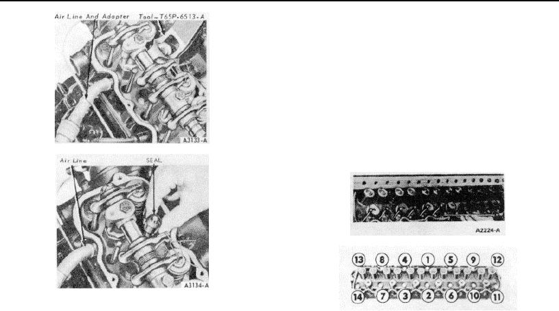
the spring washer and retainer pin. Turn off the air and
the guides and install the remaining bolts.
remove the air line and adapter. Install the spark plug and
4. The cylinder head bolts are tightened in three progressive
spark plug wire.
steps. Torque all the bolts in sequence (Figure 37) to
4. Install the rocker arm shaft by following the instructions
specifications. When cylinder head bolts have been
under Rocker Arm Installation.
tightened following this procedure, it is not necessary to
5. Clean the valve rocker arm cover and cylinder head
retorque the bolts after extended operation. However, on
gasket surfaces. Install a new gasket in the cover making
cylinder heads with composition gaskets, the bolts may be
sure the gasket tangs are securely engaged with the
checked and retorqued, if desired. Tighten the exhaust
notches in the cover. Position the cover on the head.
manifold flange attaching nuts to specification.
Install and tighten the cover attaching bolts in two steps.
5. Apply Lubriplate or equivalent to both ends of the push
First, torque the bolts to specifications. Two minutes later,
rods.
Install the push rods in the original bores,
torque the bolts to the same specifications.
positioning the lower end of the rods into the tappet
6. Insert the regulator valve (with the vent hose attached)
sockets. Apply Lubriplate or equivalent to the valve stem
into the valve rocker arm cover mounting grommet. Install
tips and to the rocker arm pads.
the air cleaner.
6. Install the valve rocker arm shaft assembly following
CYLINDER HEAD
procedures under Valve Rocker Arm Shaft Installation.
Check the valve clearance, following the procedure
Removal
outlined
under
Valve
Clearance
Adjustment.
1. Drain the cooling system. Remove the air cleaner.
Disconnect the radiator upper hose.
2. Disconnect the throttle control cable at the carburetor.
1-18

