TM 9-6230-210-13&P
LEGEND
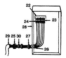
22 LEAD
23 TERMINAL STRIP
24 SCREWS (6)
25 CAP
26 ELECTRICAL
CONNECTOR
27 WASHER
(RUBBER)
28 CONTROL PANEL
29 POWER CABLE
30 WASHER (METAL)
m. Tag and identify six leads (22) from the power cable to terminal strip (23).
n. Loosen six screws (24) and remove leads.
o. Unscrew cap (25) from electrical connector (26) and remove beveled rubber washer (27) from control panel (28).
p. Withdraw power cablee (29) and remove beveled rubber washer (30) and cap (25) from power cable (29).
q. Replace defective parts.
r. Place cap (25), metal washer (30), and beveled robber washer (27) over end of power cable (29).
s. Insert power cable into control panel (28).
t. Install six leads on terminal strip (23) and tighten screws (24).
u. Remove tags.
v. Secure power cable to control panel by tightening cap (25) onto connector (26).
w. Install control panel inner rover (21) and secure with assembled screw (20).
x. Install control panel outer cover (19) and secure with two assembled screws (18).
y. Place cap (13), metal washer (15), and beveled robber washer (17) over end of power cable (12).
z. Insert power cable into junction box (16).
NOTE
Remove tags after next two steps are completed.
aa. Connect blue, green, and white leads and screw on wire nuts (11).
ab. Connect remaining three leads from power cable to receptacle.
ac. Tighten terminal screws (10).
4-50