TM 9-2610-200-14
2-46
CHAPTER 2. CARE, MAINTENANCE, AND INSPECTION (Con't)
SECTION III. UNIT MAINTENANCE (Con't)
2-29. RUNFLAT TIRE MAINTENANCE (HMMWV) (Con't).
c. ASSEMBLY (Con't)
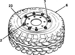
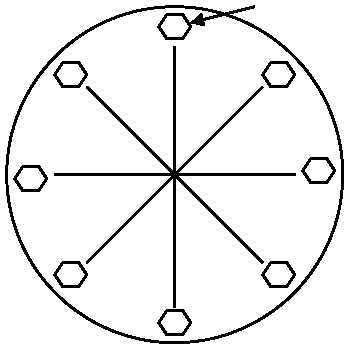
12. Torque eight self-locking nuts (1) to 65 Ib.-
ft, (88 N.m) in sequence shown.
13. Check wheel assembly for gaps at each stud
(9) between rim halves (2 and 8) .Use a 0.0015
inch (0.038 mm) thickness gage (e.g. spark plug
gap feeler gage) to detect gaps. If gaps are
detected, disassemble and assemble wheel
assembly and check for gaps. If gaps are still
detected, replace rim half (2).
14. Install valve core (4) in valve stem (3) (see
paragraph 2-26).
WARNING
Never inflate a wheel assembly without having checked wheel locknut torque's to ensure that
the wheel locknuts are tightened to specification. An assembly with improperly tightened
locknuts could separate under pressure, resulting in serious injury or death.
Always use a tire inflation safety cage when inflating tires. Stand to one side of the cage during
inflation, never directly in front. Keep hands out of cage during inflation. Inflate assembly to
recommended pressure using a pneumatic tire inflator-gage. Do not exceed 30 psi (207 kPa) cold
inflation pressure. Failure to follow these instructions may result in serious injury or death.
15. Place assembly in an inflation safety cage (see
paragraph 2-3} and inflate tire (6} to 30 psi (207
kPa) to seat tire bead.
16. Inflate tire (1) to recommended pressure (see
TM 9-2330-280-10).
17. Check for leaks around rim edges (23) and valve
stem (3) using a detergent and water solution.
FOLLOW-ON TASKS:
Install wheel (TM 9-2320-280-20).
5
8
2
3
6
7
4
1
1