TM 9-2330-238-14
4-22. DOOR-OPERATED BLACKOUT SWITCHES REPLACEMENT
This Task Covers:
a.
Removal
b.
Installation
lnitia/ Setup:
Equipment Conditions:
l External power supply cable disconnected.
Tools/Test Equipment:
l General mechanic’s tool kit
Materials/Parts:
l Marker tags (Item 15, Appendix E)
NOTE
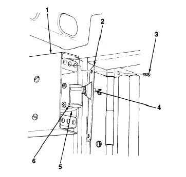
Replacement of all model door-operated blackout switches is similar. M447, M447C,
M750, and early model M313 are illustrated.
I
a.
REMOVAL
NOTE
l Ensure that 220-volt main switch located in junction box is in OFF position.
l Mounting screws for switch cover may vary between two and four for M447, M447C,
M750, early model M313, and M749, serial numbers V001 through V356 vans. On
M749, serial numbers V549 through V628, there are eleven mounting screws.
1.
2.
3.
4.
Remove screws and disconnect electrical leads
(5) from terminal board. Tag electrical leads.
Disconnect electrical leads (5) from switch termi-
nals (6). Tag electrical leads.
Remove switch (4) from switch cover (2).
M447, M447C, M750, AND M313 (EARLY MODEL)
TA701945
4-30

