TM 5-4930-244-14
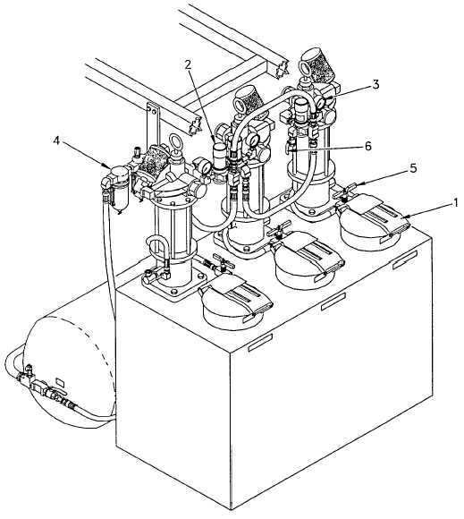
Figure 2-2. Lube Tank Assembly Controls and Indicators
b.
Lube Tank Assembly. (Refer to Figure 2-2).
(1)
Manhole Cover Latch (1). Opens the cover to each lube compartment.
(2)
Air Pressure Regulator (2). Regulates pump speed. Adjusts air pressure to the pumps.
(3)
Air Pressure Gauge (3). Displays air pressure from 0-200 psi.
(4)
Air Moisture Separator (4). Removes moisture from the air coming from the air receiver tank to the air regulators
(2).
(5)
Lube Recirculation Valve (5). Permits recirculation of lubricant from pump to compartment.
(6)
Air Pressure Relief Valve (6). Relieves air pressure in all pump lines.
2-2