
TM 5-3820-245-14&P
Figure 6-21. VALVE SECTION DISASSEMBLY INLET
3. Inspect conditions of threads in working ports. Inspect body casting for cracks. Inspect cartridge, O-Rings,
seal port in body for pits or scores.
CAUTION
Excessive wear or galling in either spool or spool bore will
require replacement of valve assembly. Spool and housing
not serviced separately.
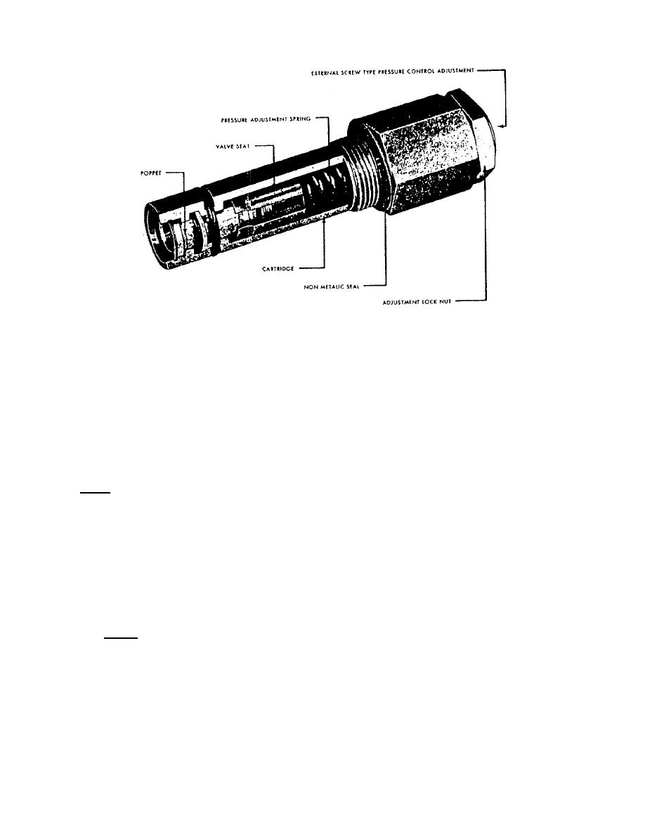
Clamp edge, (hex portion of relief valve) cartridge in a vise. Using a 1-1/2 inch open end wrench, .loosen
adjustment locknut. Unscrew external screw pressure control from cartridge and remove pressure adjusting
spring.
NOTE: There should be no spring tension on pressure control when pressure control is backed out.
Remove valve seat assembly, inspect valve for galling and scores. Replace all necessary parts. Replace O-
Rings and backup O-Rings. Coat valve section with light oil before assembly. Reinstall relief cartridge into
body.
D. Reassembly Control Valve Bank
1. After overhaul procedure for valve section is complete, you are now ready to reassemble valve bank
assembly. On a flat work bench, install O-Rings to port grooves. Four (4) O-Rings are required between
each valve section. (See Figure 6-22). Use vasoline or lubricant to hold O-Rings in position.
NOTE: Seal kit for 10 valve sections, P/N 47227.
PAGE 70
