• Home
  • Download PDF
  • Order CD-ROM
  • Order in Print
Figure 14. Rear Cylinder Hose Connection.
Figure 16. Rear Isolators.

Field Maintenance Manual For Military 621G Scraper -6 Page Navigation
  861    862    863    864    865  866  867    868    869    870    871  
img
.
TM 5-3805-296-23-6
0424
INSTALLATION CONTINUED
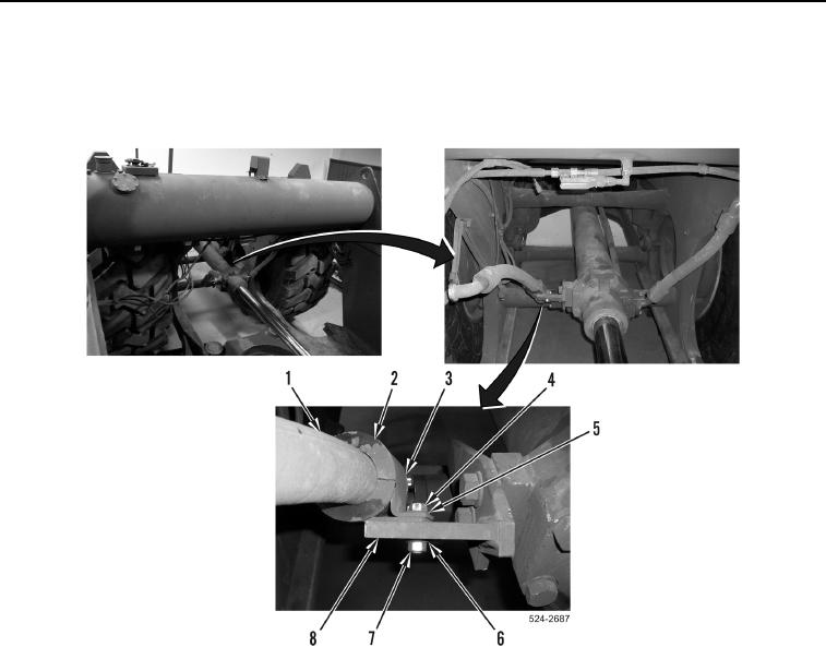
3. Install bolt (Figure 15, Item 4), washer (Figure 15, Item 5), rubber isolator (Figure 15, Item 2), hydraulic hose
clamp (Figure 15, Item 3), washer (Figure 15, Item 6), and nut (Figure 15, Item 7) on hydraulic hose
(Figure 15, Item 1) and bracket (Figure 15, Item 8).
Figure 15. Rear Hydraulic Hose Clamp.
0424
0424-15


Privacy Statement
Press Release
Contact

© Copyright Integrated Publishing, Inc.. All Rights Reserved.