
TM 5-3805-296-23-6
0420
REMOVAL CONTINUED
CAUTION
Plug and cap all hydraulic lines and fittings to prevent contamination.
NOTE
Tag and mark hydraulic lines to aid in installation.
Note routing and location of hydraulic lines to aid in installation.
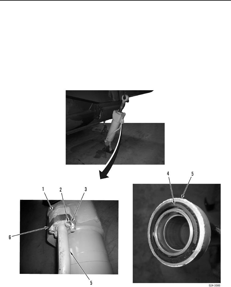
23. Remove four bolts (Figure 12, Item 3), washers (Figure 12, Item 2), two flange halves (Figure 12, Item 6), and
hydraulic line (Figure 12, Item 5) from apron cylinder (Figure 12, Item 1).
24. Remove O-ring (Figure 12, Item 4) from hydraulic line (Figure 12, Item 5). Discard O-ring.
Figure 12. Apron Cylinder Hydraulic Line.
0420