• Home
  • Download PDF
  • Order CD-ROM
  • Order in Print
Figure 2. Line to Main Control Valve Connection.
Figure 4. Air Hoses.

Field Maintenance Manual For Military 621G Scraper -6 Page Navigation
  722    723    724    725    726  727  728    729    730    731    732  
img
.
TM 5-3805-296-23-6
0418
REMOVAL CONTINUED
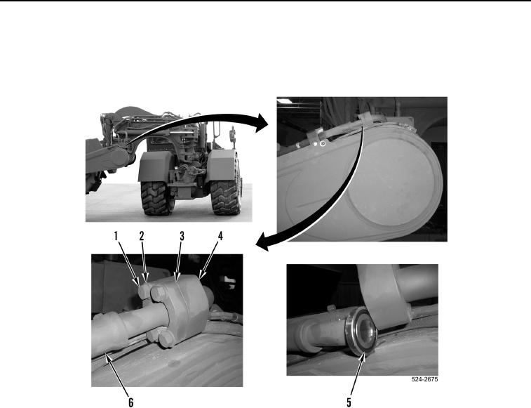
5. Remove four bolts (Figure 3, Item 1), washers (Figure 3, Item 2), two flange halves (Figure 3, Item 3), and
hydraulic hose (Figure 3, Item 6) from hydraulic line (Figure 3, Item 4).
6. Remove O-ring (Figure 3, Item 5) from hydraulic hose (Figure 3, Item 6). Discard O-ring.
Figure 3. Front Bowl Hose Connection.
0418
0418-4


Privacy Statement
Press Release
Contact

© Copyright Integrated Publishing, Inc.. All Rights Reserved.