
TM 5-3805-296-23-6
0417
PILOT CONTROL HOSES REMOVAL CONTINUED
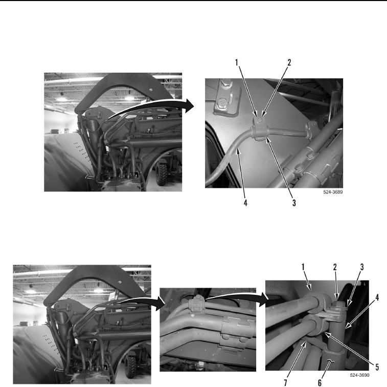
37. Remove two bolts (Figure 18, Item 2), washers (Figure 18, Item 1), and clamps (Figure 18, Item 3) from lower
right quick drop pilot control hose (Figure 18, Item 4) and machine.
Figure 18. Lower Right Quick Drop Pilot Control Hose Clamps.
0417
38. Remove bolt (Figure 19, Item 2), washer (Figure 19, Item 3), clamp (Figure 19, Item 1), clamp
(Figure 19, Item 5), spacer (Figure 19, Item 4), and P-clamp (Figure 19, Item 7) from boss (Figure 19, Item 6).
Figure 19. Draft Frame Pilot Control Hose Clamps.
0417