
TM 5-3805-296-23-6
0413
REMOVAL
000413
WARNING
Allow hydraulic system to cool before performing procedure. Hot hydraulic fluid can cause
severe burns. Wear eye, hand, and skin protection when working with heated parts.
Hydraulic oil is very slippery. Immediately wipe up any spills. Failure to follow this warning
may result in injury or death to personnel.
CAUTION
Plug and cap all hydraulic hoses and fittings to prevent contamination.
NOTE
Tag and mark hydraulic hoses to aid installation.
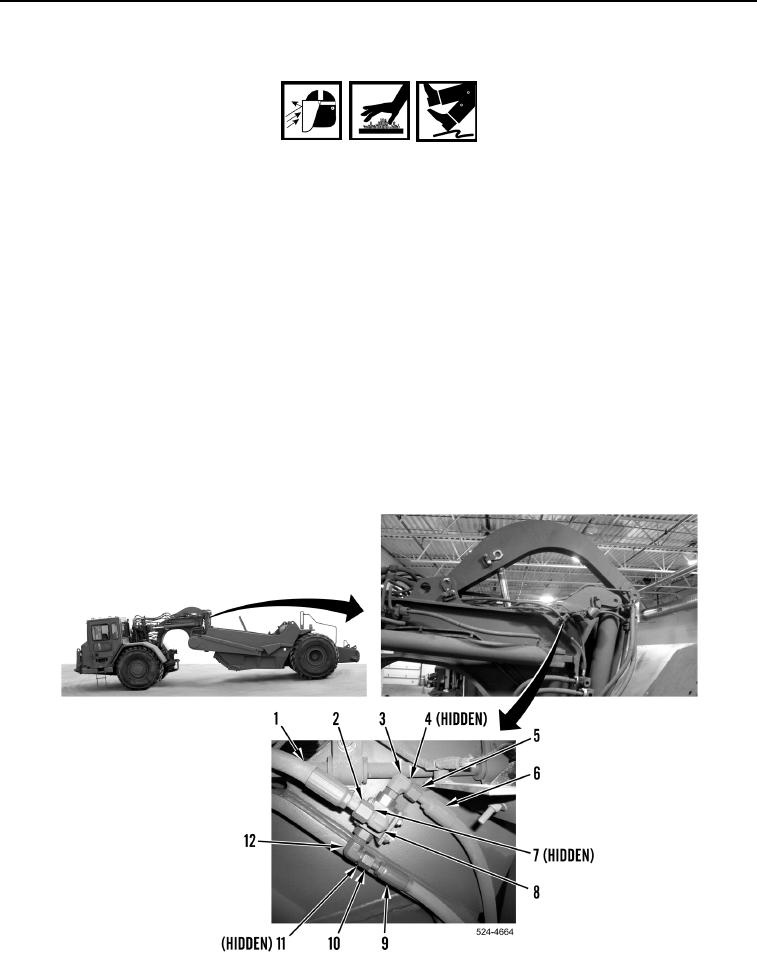
1. Loosen tube nut (Figure 1, Item 2) and remove hydraulic pilot hose (Figure 1, Item 1) and O-ring
(Figure 1, Item 7) from fitting (Figure 1, Item 8). Discard O-ring.
2. Loosen tube nut (Figure 1, Item 5) and remove hydraulic pilot hose (Figure 1, Item 6) and O-ring
(Figure 1, Item 4) from fitting (Figure 1, Item 3). Discard O-ring.
3. Loosen tube nut (Figure 1, Item 10) and remove hydraulic pilot hose (Figure 1, Item 9) and O-ring
(Figure 1, Item 11) from fitting (Figure 1, Item 12). Discard O-ring.
Figure 1. Hose Connection.
0413