
TM 5-3805-296-23-6
0407
INSTALLATION CONTINUED
NOTE
Remove all plugs and caps from hydraulic hoses, lines, and fittings.
Install hydraulic hoses and lines as tagged and marked during removal.
Install P-clamps as noted during removal.
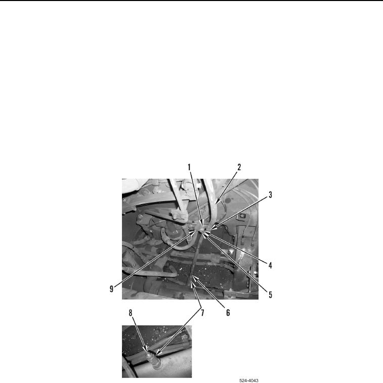
15. Position cushion hitch hydraulic hose (Figure 19, Item 2) on machine.
16. Install new O-ring (Figure 19, Item 8), cushion hitch hydraulic hose (Figure 19, Item 2) and tighten tube nut
(Figure 19, Item 6) on fitting (Figure 19, Item 7).
17. Install P-clamp (Figure 19, Item 3) on cushion hitch hydraulic hose (Figure 19, Item 2).
18. Install P-clamp (Figure 19, Item 3), spacer (Figure 19, Item 1), P-clamp (Figure 19, Item 9), washer
(Figure 19, Item 4) and bolt (Figure 19, Item 5) on machine.
Figure 19. Cushion Hitch Hydraulic Inboard Hose Connection.
0407