
TM 5-3805-296-23-6
0405
REMOVAL CONTINUED
NOTE
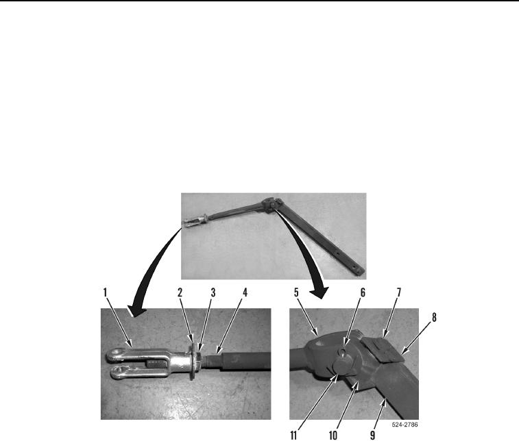
Note position of jam nut to aid in installation.
5. Loosen jam nut (Figure 3, Item 3), remove clevis (Figure 3, Item 1), washer (Figure 3, Item 2), and jam nut from
rod (Figure 3, Item 4).
6. Remove cotter pin (Figure 3, Item 6), pivot pin (Figure 3, Item 11), and rod (Figure 3, Item 5) from pivot block
(Figure 3, Item 10). Discard cotter pin.
7. Remove cotter pin (Figure 3, Item 8), pivot pin (Figure 3, Item 7), and pivot block (Figure 3, Item 10) from rod
(Figure 3, Item 9). Discard cotter pin.
Figure 3. Spring Linkage.
0405