
TM 5-3805-296-23-6
0403
INSTALLATION CONTINUED
NOTE
Install P-clamps as noted during removal.
Install tiedowns as noted during removal.
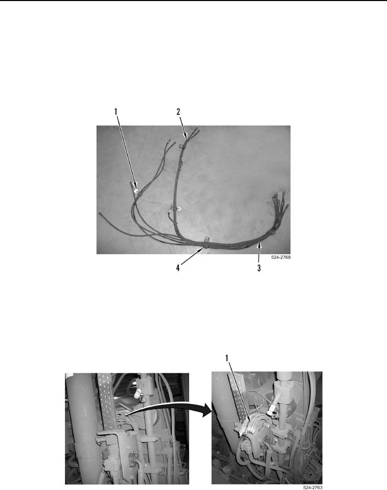
13. Install seven tiedown straps (Figure 32, Item 2) on lubrication hoses (Figure 32, Item 3).
14. Install two large P-clamps (Figure 32, Item 4) on lubrication hoses (Figure 32, Item 3).
15. Install three small P-clamps (Figure 32, Item 1) on lubrication hoses (Figure 32, Item 3).
Figure 32. Right Side Lubrication Hose Tiedowns.
0403
NOTE
Install lubrication hoses as noted during removal.
16. Position eight lubrication hoses (Figure 33, Item 1) on machine.
Figure 33. Right Side Lubrication Hoses.
0403