
TM 5-3805-296-23-6
0403
REMOVAL CONTINUED
NOTE
Note location and routing of lubrication hoses to aid in installation.
27. Remove four lubrication hoses (Figure 7, Item 1) from machine.
Figure 7. Left Side Lubrication Hoses.
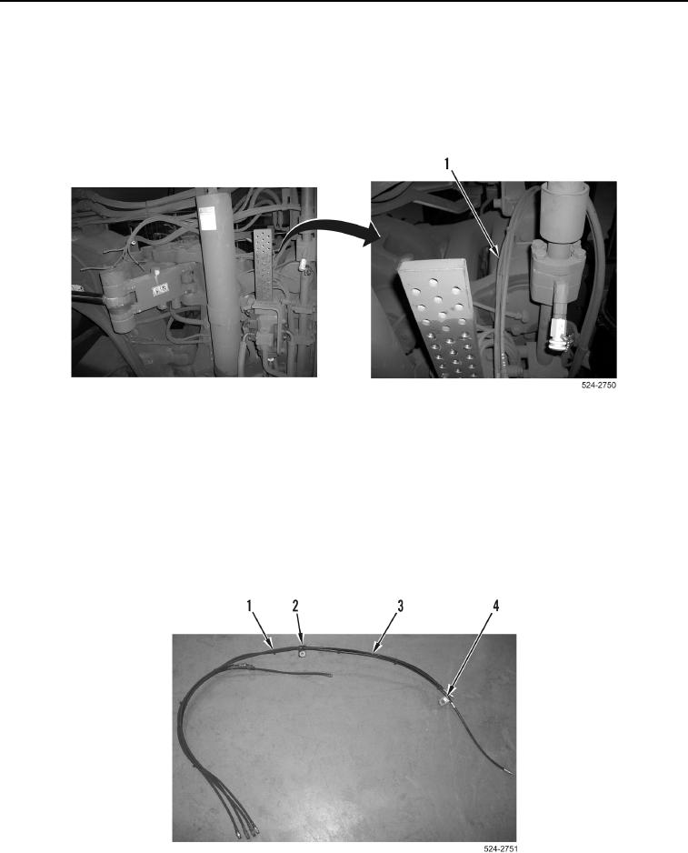
0403
NOTE
Note location of P-clamps to aid in installation.
Note location and quantity of tiedowns to aid in installation.
28. Remove two large P-clamps (Figure 8, Item 4) from lubrication hoses (Figure 8, Item 3).
29. Remove small P-clamp (Figure 8, Item 2) from lubrication hoses (Figure 8, Item 3).
30. Remove seven tiedown straps (Figure 8, Item 1) from lubrication hoses (Figure 8, Item 3).
Figure 8. Left Side Lubrication Hose Tiedowns.
0403