
TM 5-3805-296-23-6
0400
INSTALLATION CONTINUED
NOTE
Install wiring harness as noted during removal.
Install P-clamp as noted during removal.
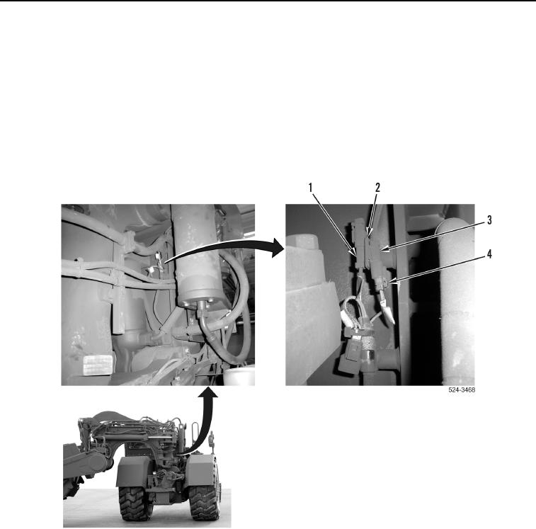
2. Route transmission cushion hitch wiring harness (Figure 11, Item 2) on machine.
3. Slide connector (Figure 11, Item 1) downward on bracket (Figure 11, Item 2).
4. Install cushion hitch wiring harness connector (Figure 11, Item 4) on cushion hitch solenoid connector
(Figure 11, Item 3).
Figure 11. Right Side of Machine Behind Cab.
0400