
TM 5-3805-296-23-6
0400
REMOVAL CONTINUED
NOTE
Note routing of wiring harness to aid in installation.
Note location of tiedown straps to aid in installation.
Note location of P-clamps to aid in installation.
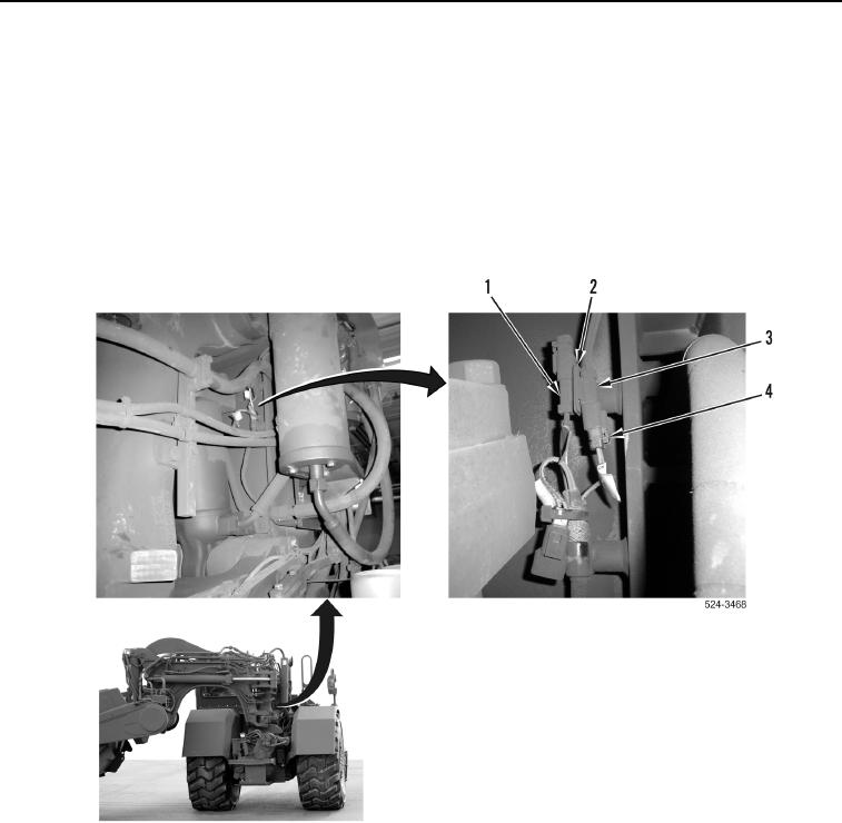
2. Disconnect cushion hitch wiring harness connector (Figure 2, Item 4) from cushion hitch solenoid connector
(Figure 2, Item 3).
3. Slide cushion hitch wiring harness connector (Figure 2, Item 1) up and remove from bracket (Figure 2, Item 2).
Figure 2. Right Side of Machine Behind Cab.
0400