
TM 5-3805-296-23-6
0393
DISASSEMBLY CONTINUED
NOTE
Note location and position of fitting to aid in installation.
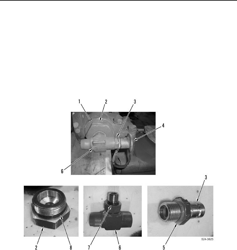
11. Remove dust cover (Figure 11, Item 4) from test port (Figure 11, Item 3).
12. Remove test port (Figure 11, Item 3) from fitting (Figure 11, Item 6).
13. Remove O-ring (Figure 11, Item 5) from test port (Figure 11, Item 3). Discard O-ring.
14. Remove fitting (Figure 11, Item 6) from fitting (Figure 11, Item 2).
15. Remove O-ring (Figure 11, Item 7) from fitting (Figure 11, Item 6). Discard O-ring.
16. Remove fitting (Figure 11, Item 2) from hydraulic and steering pump manifold (Figure 11, Item 1).
17. Remove O-ring (Figure 11, Item 8) from fitting (Figure 11, Item 2). Discard O-ring.
Figure 11. Test Port with Fitting.
0393