
TM 5-3805-296-23-5
0355
INSTALLATION
000355
WARNING
Wheels must remain chocked during entire procedure. Failure to follow this warning may
result in injury or death to personnel.
NOTE
Remove plugs and caps from air hoses and fittings.
Install air hoses as noted during removal.
Install air hoses as tagged and marked during removal.
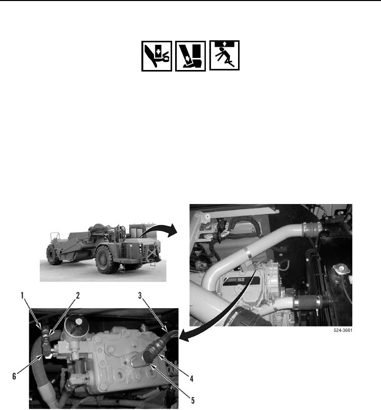
1. Position air hose (Figure 12, Item 3) on machine, install air hose on fitting (Figure 12, Item 5), and
tighten tube nut (Figure 12, Item 4).
2. Position air hose (Figure 12, Item 1) on machine, install air hose on fitting (Figure 12, Item 6), and tighten tube
nut (Figure 12, Item 2).
Figure 12. Compressor Lines.
0355