
TM 5-3805-296-23-5
0327
INSTALLATION
000327
NOTE
Remove all plugs and caps from hydraulic hoses, lines, and fittings.
Install hydraulic hoses as noted during removal.
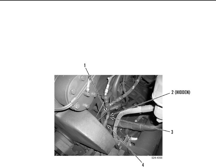
1. Position hose (Figure 9, Item 4) on machine.
2. Install new O-ring (Figure 9, Item 2), hose (Figure 9, Item 4) and tighten tube nut (Figure 9, Item 3) on fitting
(Figure 9, Item 1).
Figure 9. Hydraulic Hose.
0327