
TM 5-3805-296-23-5
0324
INSTALLATION CONTINUED
NOTE
Remove plugs and caps from hydraulic line and fitting.
Install hydraulic line as tagged and marked during removal.
Install bolts as noted during removal.
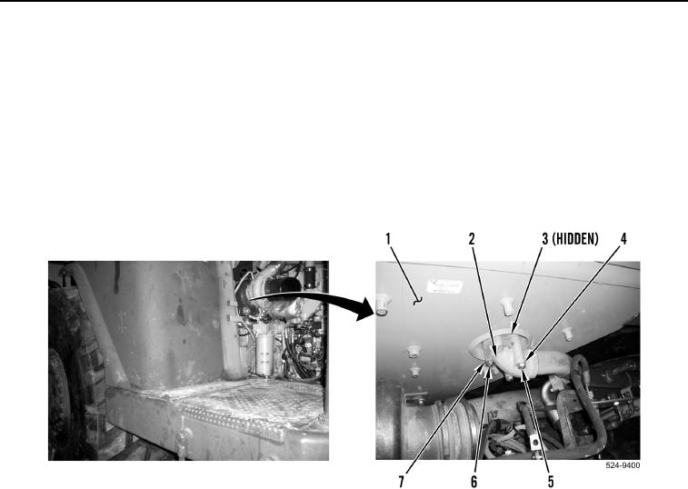
14. Install new O-ring (Figure 53, Item 3), elbow (Figure 53, Item 2), two washers (Figure 53, Item 4), and bolts
(Figure 53, Item 5) on hydraulic oil tank (Figure 53, Item 1). Discard O-ring.
15. Install two washers (Figure 53, Item 7) and bolts (Figure 53, Item 6) on elbow (Figure 53, Item 2).
Figure 53. Rear Hydraulic Connection.
0324