• Home
  • Download PDF
  • Order CD-ROM
  • Order in Print
Figure 22. Hydraulic Oil Fill Cap.
Figure 24. Hose Clamps.

Field Maintenance Manual For Military 621G Scraper -5 Page Navigation
  421    422    423    424    425  426  427    428    429    430    431  
img
.
TM 5-3805-296-23-5
0324
DISASSEMBLY CONTINUED
NOTE
Note position and orientation of upper cover to aid in installation.
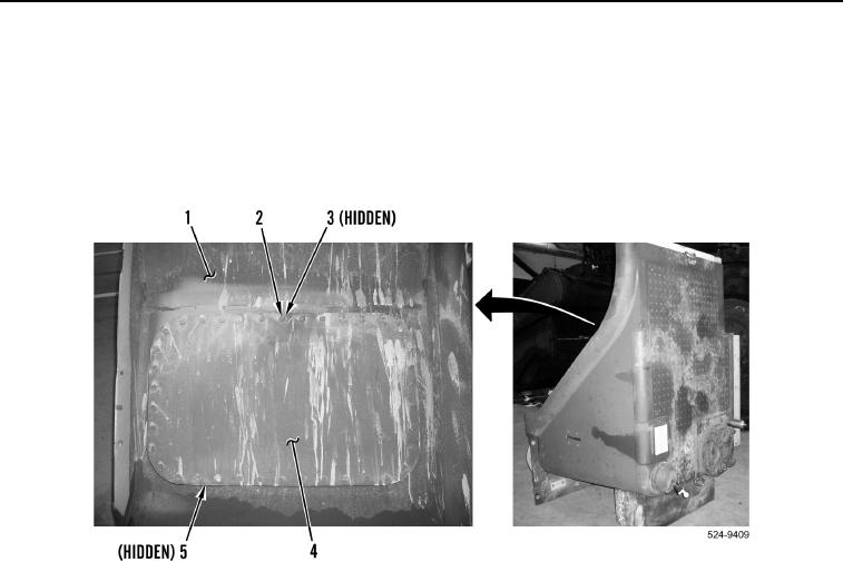
8. Remove 38 bolts (Figure 23, Item 2), locknuts (Figure 23, Item 3), upper cover (Figure 23, Item 4), and gasket
(Figure 23, Item 5) from hydraulic tank (Figure 23, Item 1). Discard locknuts and gasket.
Figure 23. Upper Cover.
0324
0324-22


Privacy Statement
Press Release
Contact

© Copyright Integrated Publishing, Inc.. All Rights Reserved.