
TM 5-3805-296-23-5
0304
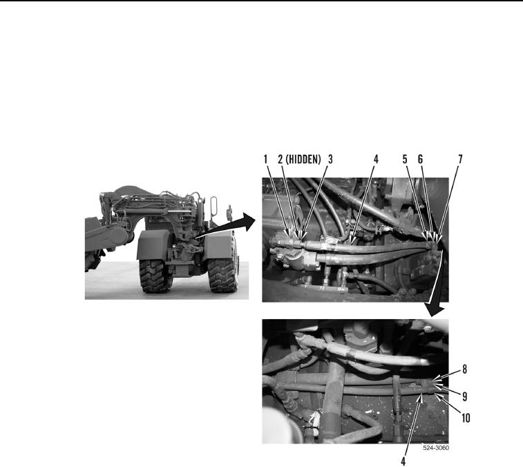
HOSE INSTALLATION CONTINUED
5. Install P-clamp (Figure 7, Item 10) on hydraulic hose (Figure 7, Item 4).
6. Install P-clamp (Figure 7, Item 10), washer (Figure 7, Item 9), and bolt (Figure 7, Item 8) on machine.
7. Install P-clamp (Figure 7, Item 5) on hydraulic hose (Figure 7, Item 4).
8. Install P-clamp (Figure 7, Item 5), washer (Figure 7, Item 7) and bolt (Figure 7, Item 6) on machine.
9. Install new O-ring (Figure 7, Item 2) on fitting (Figure 7, Item 1).
10. Install hydraulic hose (Figure 7, Item 4) on fitting (Figure 7, Item 1), tighten tube nut (Figure 7, Item 3).
Figure 7. Hydraulic and Steering Pump Hose.
0304
END OF TASK