
TM 5-3805-296-23-5
0302
INSTALLATION CONTINUED
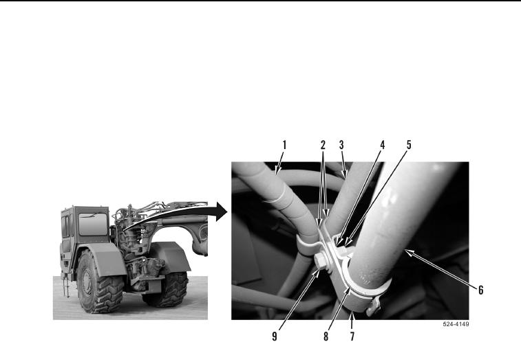
18. Install P-clamp (Figure 13, Item 2) on hydraulic hose (Figure 13, Item 3).
19. Install two P-clamps (Figure 13, Item 2) and hydraulic hoses (Figure 13, Items 1 and 3) on clamp
(Figure 13, Item 7).
20. Install two P-clamps (Figure 13, Item 2), washers (Figure 13, Item 4), bolt (Figure 13, Item 9), and nut
(Figure 13, Item 5) on clamp (Figure 13, Item 7) and grommet (Figure 13, Item 8) on hydraulic line
(Figure 13, Item 6).
Figure 13. Hitch.
0302