
TM 5-3805-296-23-4
0279
HITCH LINES INSTALLATION CONTINUED
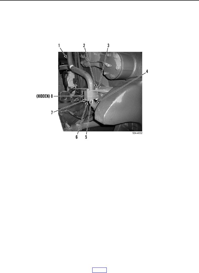
2. Install two washers (Figure 31, Item 3) and bolts (Figure 31, Item 2) on machine.
3. Install new O-ring (Figure 31, Item 8) on hitch hose (Figure 31, Item 4).
4. Install hitch hose (Figure 31, Item 4), split flange halves (Figure 31, Item 5), four washers (Figure 31, Item 7)
and bolts (Figure 31, Item 6) on hitch line (Figure 31, Item 1).
Figure 31. Hitch Line.
0279