
TM 5-3805-296-23-4
0273
INSTALLATION CONTINUED
NOTE
Route wiring harness as noted during removal.
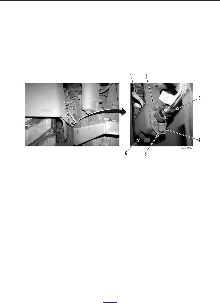
2. Position tractor actual gear switch wiring harness (Figure 7, Item 1) on housing (Figure 7, Item 6).
3. Install bracket (Figure 7, Item 2), two washers (Figure 7, Item 5), and bolts (Figure 7, Item 4) on housing
(Figure 7, Item 6).
4. Connect transmission wiring harness connector (Figure 7, Item 3) to tractor actual gear switch wiring harness
(Figure 7, Item 1).
Figure 7. Tractor Actual Gear Switch Harness and Retaining Hardware.
0273