
TM 5-3805-296-23-4
0230
REMOVAL CONTINUED
NOTE
Note location of P-clamps to aid in installation.
Note position and location of bolts.
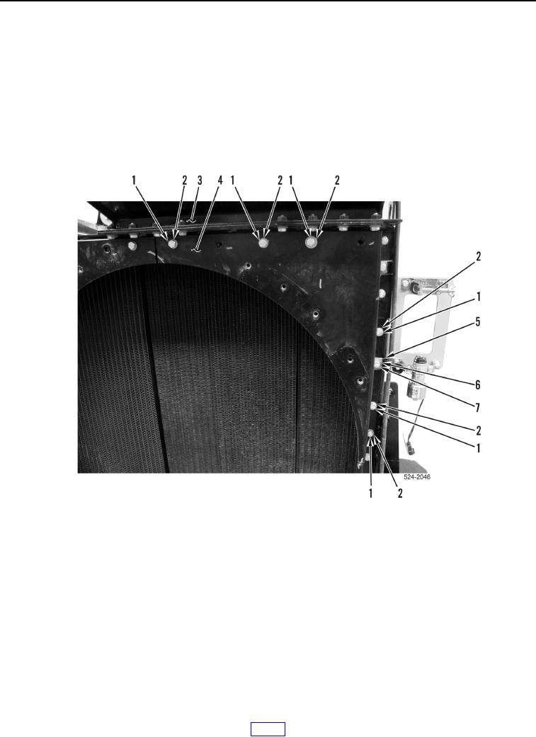
7. Remove bolt (Figure 5, Item 7), washer (Figure 5, Item 6), and P-clamp (Figure 5, Item 5) from upper right fan
shield segment (Figure 5, Item 4).
8. Remove six bolts (Figure 5, Item 1) and washers (Figure 5, Item 2) and upper right fan shield segment
(Figure 5, Item 4) from cooling pack assembly (Figure 5, Item 3).
Figure 5. Upper Right Fan Shield Segment.
0230