
TM 5-3805-296-23-4
0229
FUEL SUPPLY LINE REMOVAL CONTINUED
5. Remove bolt (Figure 3, Item 4), washer (Figure 3, Item 3), and P-clamp (Figure 3, Item 2) from hydraulic oil
tank (Figure 3, Item 1).
Figure 3. P-clamp and Hydraulic Oil Tank.
0229
NOTE
Note location and orientation of P-clamps to aid in installation.
Note location and orientation of fuel hoses to aid in installation.
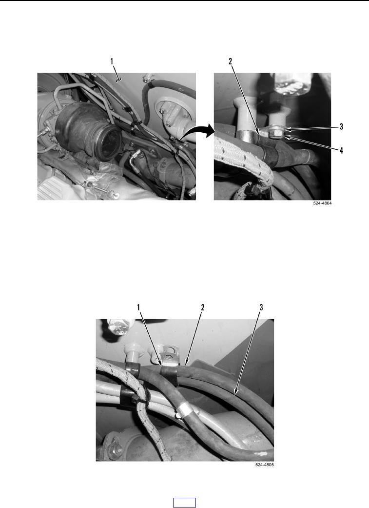
6. Remove P-clamp (Figure 4, Item 1) from fuel transfer pump fuel supply hose (Figure 4, Item 3) and fuel
transfer pump fuel return hose (Figure 4, Item 2).
Figure 4. P-clamp and Fuel Hose.
0229