
TM 5-3805-296-23-4
0228
FUEL SUPPLY LINE INSTALLATION CONTINUED
NOTE
Install P-clamps in locations noted during removal.
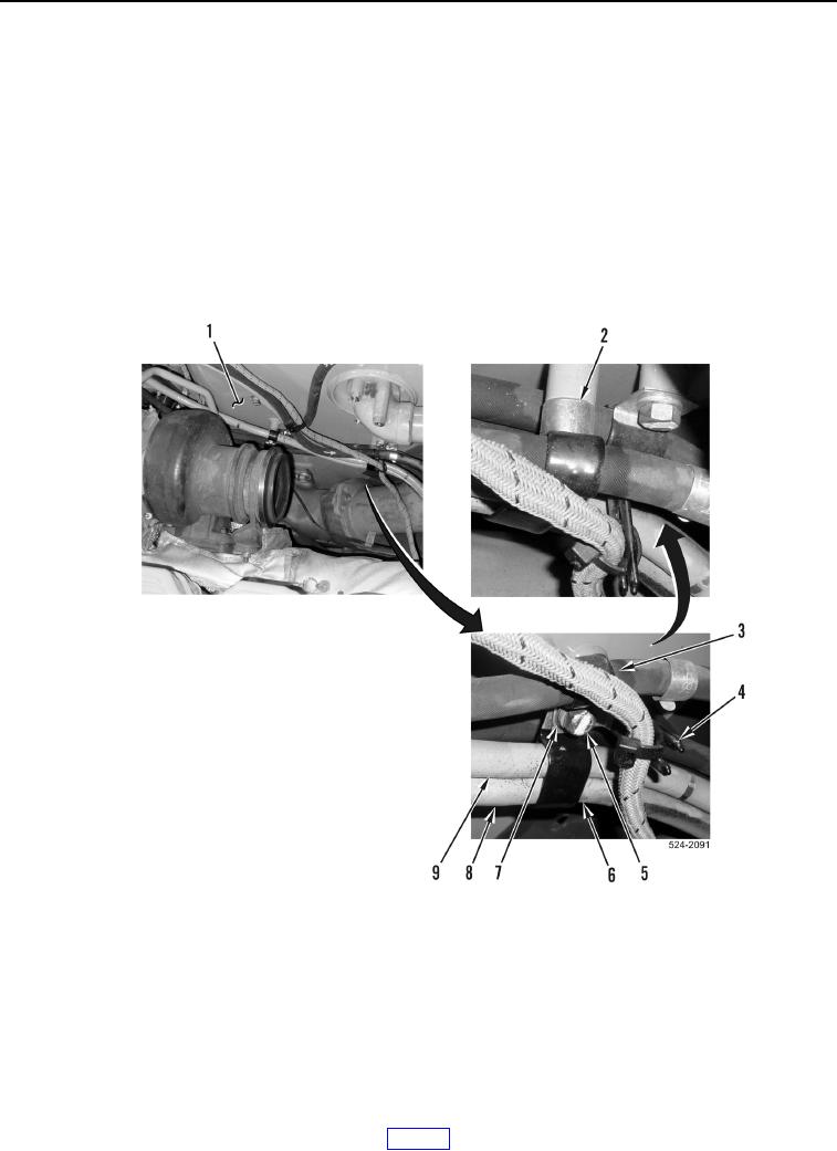
Route and install fuel hoses as noted during removal.
20. Position P-clamp (Figure 25, Item 6) on cylinder head fuel return hose (Figure 25, Item 9) and cylinder head
fuel supply hose (Figure 25, Item 8).
21. Position spacer (Figure 25, Item 2), two P-clamps (Figure 25, Items 3 and 6), and ladder clip (Figure 25,
Item 4) on hydraulic oil tank (Figure 25, Item 1).
22. Install bolt (Figure 25, Item 5), washer (Figure 25, Item 7), two P-clamps (Figure 25, Items 3 and 6), ladder clip
(Figure 25, Item 4), and spacer (Figure 25, Item 2) on hydraulic oil tank (Figure 25, Item 1).
Figure 25. P-clamps and Ladder Clip.
0228