TM 9-2330-359-14&P
Assembly and Installation
GENERAL WELDING NOTES
Welding to be done in accordance with MIL-
STD-1261, CLASS 2. All fillet welds to be 1/8-inch
minimum.
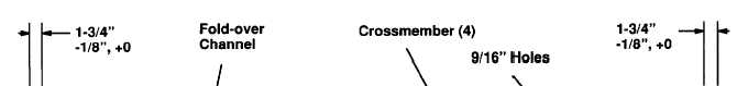
1. Space and position four crossmembers as shown with concave or sunken sides facing fold-over channel. Make
sure both outboard crossmembers have drilled holes and hole ends are positioned by channel cut-outs. Weld each
crossmember to channel, using four skip welds on each side and full welds on each end. Skip welds are approximately
1-1/2 inch long with 2- inch spacing between welds.
WARNING
Bulkhead extension weighs 80 to 90 Ibs. To avoid
injury, use two people to lift and position the exten-
sion.
2. Lift and position fold-over channel on bulkhead.
NOTE
Make sure fold-over channel is on the straight verti-
cal before welding hinge fold-overs. Otherwise,
hinge will misalign and channel will not fold down.
5-26 Change 1