
TM 5-3820-245-14&P
B. Disassembly of Control Valve Bank
1. Plug all open ports in valve bank assembly to prevent dirt and foreign matter from entering the valve bank
assembly. Clean the outside of the valve bank assembly before starting disassembly.
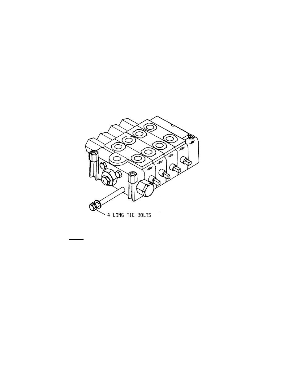
2. Place valve bank assembly on a flat work bench. To separate the individual valves and inlet and outlet
sections, unscrew the four long tie bolts. Inspect the complete valve bank for cracks. Separate the
various sections and remove and discard the O-Rings that fit between the sections.
CAUTION
The inlet and outlet sections are different from the control
flow valve sections.
They are identified by numbers
stamped on the port closest to the lever end of the valve.
3. Disassembly shall be limited to the removal of parts required to replace O-Rings, springs and poppet
sleeves. Replacement of parts other than these is not usually required, nor is it recommended.
Pull valve sections apart noting the location and position of each valve section.
NOTE: SEE PARTS MANUAL FOR PART NUMBERS.
Figure 6-3. CONTROL VALVE BANK ASSEMBLY - TIE BOLTS
PAGE 68

